







PCB DPM Scanner for Micro Data Matrix
In electronics manufacturing, the reliability of your traceability system often depends not on how powerful your MES is, but on whether that first code on the board can be read in one shot. As PCBs push toward higher density and miniaturization, Data Matrix codes are laser-etched onto green solder mask, black solder mask, copper foil, and even curved metal surfaces — shrinking to 2–3 mil, barely visible to the naked eye. Ordinary retail-grade scanners largely fail here: missed reads, misreads, endless refocusing — eventually forcing production lines back to the old "manual SN entry" approach. This article takes an engineering perspective to break down why PCB micro-codes are difficult to read, what hard capabilities an industrial DPM scanner must have, how to deploy fixed-mount versus handheld scanners by workstation, and how to verify performance before going live.
1. Why Are PCB Micro Data Matrix Codes So Hard to Read?
The problem isn't the decoding algorithm alone — it's the layering of optics, marking process, and production line speed.
Extremely low contrast, sometimes even "yin-yang reversal"
Codes laser-etched onto solder mask can be light marks on a dark board (negative code) or dark marks on a light board (positive code). The grayscale relationship is completely opposite — traditional fixed-threshold algorithms can only handle one side.
The background isn't blank paper — it's a "visual noise field"
PCB surfaces are covered with copper traces, silkscreen text, pads, and vias. The Data Matrix is often squeezed into a few square millimeters of empty space. Algorithms easily mistake traces for code cells.
Reflectivity and material variety
Glossy solder mask, exposed copper pads, gold fingers, metal shields — a single board contains multiple reflective properties. Direct ring light creates specular reflections that "wash out" the code area, leaving the sensor with nothing but a bright spot.
Too small, too dense, and moving
In the era of 01005/008004 components, code cell sizes approach 0.05 mm. When boards pass high-speed stations, rolling shutters create motion blur — once the fine detail smears, decode rates collapse.
Marking tolerances are real
Laser power drift, defocus, and parameter variation cause code depth to fluctuate from one board to the next. Add reflow warpage and flux residue, and the actual production environment is far harsher than any lab sample.
In short: PCB DPM is not a "barcode recognition problem." It is a machine vision problem of reconstructing damaged grids in complex optical scenes.
2. Four Hard Capabilities an Industrial DPM Scanner Must Have
To pull the first-pass read rate (FPRR) to an acceptable level for production lines, the device can't rely on "high pixel count" alone. It needs all four of the following:
2.1 High-Resolution Global Shutter Imaging
Sensor: at least 1.3 MP, global shutter (not rolling shutter) to eliminate motion blur on fast-moving boards
Optical resolution: must distinguish 2.0 mil or smaller cells, with an industrial-grade lens (not a generic one)
For micro-codes, "seeing clearly" matters more than "more pixels" — wasting pixels at the wrong focal distance is meaningless
2.2 Multi-Spectrum + Controllable Illumination
Switchable red/white/blue light sources: red suppresses copper foil reflections, blue enhances shallow etched code contrast, white handles standard flat surfaces
Supports dark field, diffuse dome, and polarized combinations to suppress specular highlights rather than "blasting them with more light"
Adjustable light angle for automatic optimization based on board color and mark depth
2.3 AI Image Preprocessing and Fault-Tolerant Decoding
Adaptive threshold segmentation: handles positive and negative codes in the same frame without manual parameter switching
Dynamic contrast normalization: pulls out codes with less than 20% grayscale difference
ECC200 error correction: tolerates dot breakage, oil contamination, and up to 25% code cell loss
Background suppression: isolates the "true code region" from copper traces and silkscreen rather than brute-force decoding the entire image
2.4 Production-Line Integration and Triggering
IO/PLC trigger, photoelectric sensor coordination — millisecond-level "capture → decode → verdict → upload to MES" cycle
Supports Ethernet/IP, Profinet, Modbus TCP, and other industrial protocols
Clear strategy for no-read events: auto-rescan → alternate angle/lighting → reject station — never allow "skip and pass"
3. Fixed-Mount vs Handheld: Choose by Workstation First, Then by Device
Neither architecture is inherently superior — the question is whether it matches the process flow.
| Dimension | Fixed-Mount Industrial Reader | Handheld DPM Scanner |
| Typical workstation | SMT pass-through, test fixture, panel exit | Repair, incoming QC, rework, high-mix low-volume |
| Cycle time | Milliseconds, no human intervention | Manual trigger, seconds |
| Pose tolerance | Requires mechanical fixturing, relies on optical field coverage | Operator can adjust angle, find reflection-free zones |
| Strength | Stable, repeatable, continuous data | Flexible, covers blind spots, easy to rescan |
| Weakness | Changeover requires reconfiguring mounting | Dependent on operator skill |
Rule of thumb:
High-speed, fixed-position, same-spec continuous runs → Fixed-mount
Random part orientation, parts that need flipping, rework traceability → Handheld
In practice, most lines run "fixed-mount for main line cycle + handheld for backup rescan"
4. Scenario-Based Device Selection
4.1 Fixed Workstation: Let the Board Come to the Lens
On SMT post-production, PCBA test fixtures, and automated sorting stations, the biggest fear is human variability — the same code reads fine today but fails tomorrow.
An ideal fixed-mount solution should make these three things default capabilities:
Plug-and-play adaptation: Automatically handles different batch board colors, positive/negative codes, shallow/deep etching — no engineer needed for constant parameter tweaking
No dropped frames on micro-codes: Global shutter + high-resolution sensor freezes 2.0 mil Data Matrix codes clearly even during dynamic pass-through
Self-selecting illumination: Red/white light switches automatically based on background, separating code cells from the solder mask layer on complex backgrounds
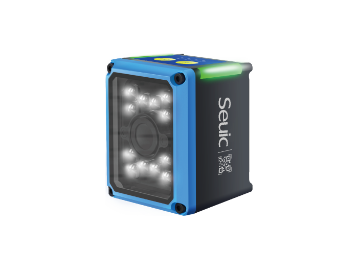
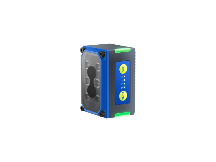
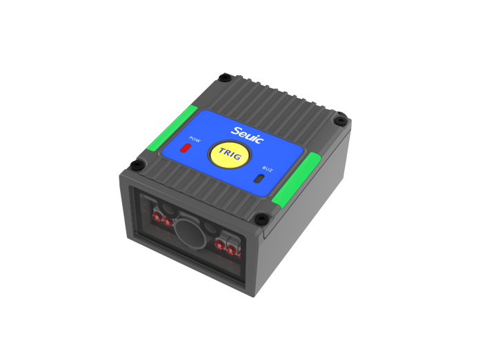
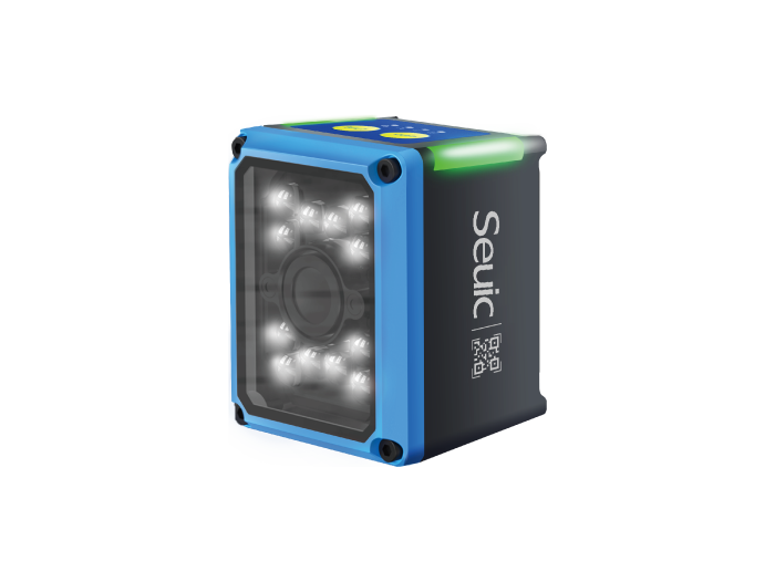
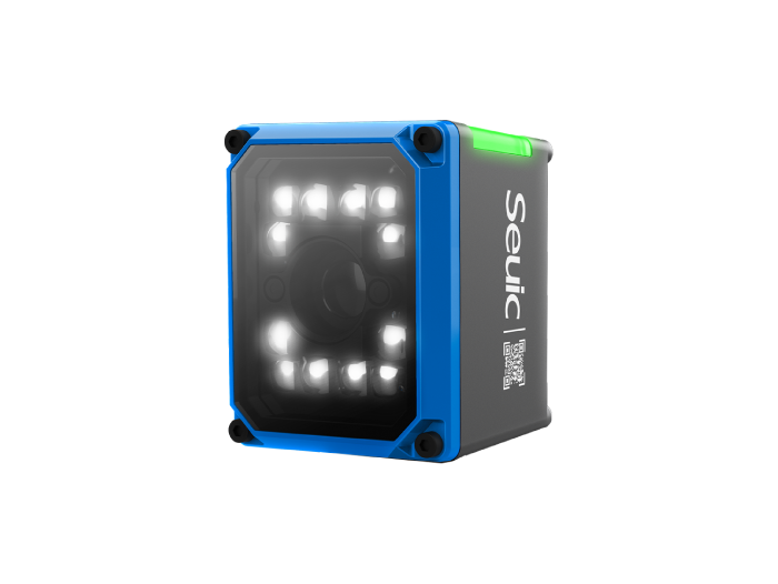
Following this logic, a new generation of AI-powered fixed-mount readers has shifted deployment from "parameter tuning" to "self-learning." Take the SEUIC X4 AI fixed industrial reader as an example — its focus isn't spec-stacking, but reducing on-site engineering costs:
AI-driven zero-configuration deployment
Octa-core AI chip + adaptive image segmentation. Powers on and automatically locks onto the code region. Handles positive/negative codes, low contrast (down to 10%), and curved reflective codes with dynamic optimization. Achieves parameter self-adaptation in about 1 second — no dedicated technician needed for light and focus adjustment.
Micro-code optical foundation
1.3 MP global shutter CMOS, minimum 2.0 mil 2D code support, dual laser aiming, 50–1000 mm focus range — covering SMT lines, test fixtures, and automated equipment integration.
Native production-line interfaces
Supports Ethernet/IP, Profinet, Modbus TCP, RS232/RS485. IP67 rated. Direct PLC/MES integration. Dynamic code reading at up to 3 m/s, matching high-speed pass-through cycles.
Best fit: Panel multi-code reading, varying solder mask colors, automated stations where "set it and forget it" is the goal.
4.2 Mobile Workstation: When the Line Needs a Person to Reach the Code
Repair benches, incoming IQC, rework areas, prototype traceability — here, boards aren't always facing up. Codes may be on the inside of metal frames, in heatsink crevices, or on curved laser-etched surfaces. Fixed lenses can't reach them. You need a "smart" handheld gun.
The key for this type of handheld DPM device isn't "can it scan labels?" but:
Switches light paths when encountering reflections instead of making the operator tilt their head to find the angle
Still locks onto codes that are deformed, scratched, or warped after reflow
Ergonomic feel and trigger logic suited for thousands of actuations per shift
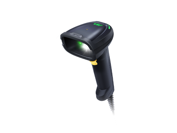
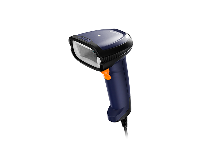
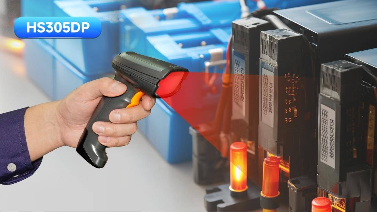
Corresponding to specific products, the SEUIC HS305DP wired AI DPM handheld scanner is well-suited for 3C electronics and PCBA repair scenarios:
Dual-core AI + tri-color intelligent diffuse illumination
Red/white/blue light sources switch automatically or manually based on material: blue light suppresses metal curved-surface reflections, red light penetrates light-colored substrates, white light handles standard printing — solving the persistent blind spot of "reflective curved surfaces that won't scan."
Micro-code and distortion tolerance
1280×1080 global shutter, 60 fps, DPM-specific lens. Reads 5 mil Data Matrix codes. Features dedicated AI fault tolerance for twisted, pitted, low-contrast, and thermally deformed codes. Wide-angle reading: ±60° pitch, ±55° skew — no need to align perfectly.
Industrial-grade ergonomics
~162 g ergonomic body, IP54 protection, 1.8 m drop resistance. Tri-directional LED status feedback. RS232/USB direct connection to MES. Designed for high-frequency trigger operations over long shifts.
Best fit: Repair traceability, high-mix low-volume production, fixed-reader blind-spot rescanning, incoming sampling.
5. Selection Checklist and PoC Recommendations (Mandatory Before Go-Live)
Don't rely on spec sheets alone. What really determines read rates is the "bad samples" from your own production line.
5.1 Sample Collection Checklist
20 normal good codes
10 low-contrast / yin-yang codes
10 reflow-warped codes
5 oil-contaminated / flux-residue codes
5 from each different supplier and laser batch
Edge tolerance samples (misaligned codes, shallow etching, over-deep marking)
5.2 PoC Verification — 6 Steps
Confirm code symbology and minimum cell size (mil/mm)
Record marking process parameters (laser power, speed, focal distance)
Fixed-mount test: mounting distance, field of view, trigger delay, rescan strategy
Handheld test: first-pass read rate at different angles and light source settings
Run 500–1000 real boards, collect statistics on FPRR / rescan rate / missed read rate — not just "can it decode?"
Verify exception closure: does a no-read trigger a reject lane? Is a traceability log written? Is there a manual fallback that doesn't lose data?
5.3 Acceptance Thresholds
First-pass read rate target: ≥ 99.9% (critical stations)
No "skip on no-read" allowed
Parameters are reproducible after locking — rate stays consistent across shift and operator changes
MES disconnect has local cache and retransmission mechanism
A micro Data Matrix on a PCB isn't a question of "can it be scanned." It is the trust anchor of your entire production line traceability system. When selecting a DPM scanner, don't be misled by "pixel count" and "decode speed." What really determines the first-pass read rate is: whether the illumination adapts to the material, whether the algorithm can reconstruct damaged codes, and whether the device integrates seamlessly into your line cycle. Fixed-mount readers guard the main line. Handheld scanners provide flexibility. And running a PoC with real defective samples is the only way to turn "scanning" into a truly reliable digital entry point.
If you are evaluating a PCB DPM reading solution, feel free to contact SEUIC. We will arrange one-on-one expert service and you can apply for a free product trial.
Related News

-

Double Efficiency High-Bay Inventory: Normal vs Ultra-Long Range UHF RFID Handheld
Product Updates | 2026.11.04Learn More
-

India RFID Supplier Selection: Industrial Procurement & Audit Guide
Product Updates | 2026.11.04Learn More
-

RFID Inventory for Beverages & Fresh Food: Handheld Reader Selection Guide
Product Updates | 2026.11.04Learn More
-

RFID Manufacturer Selection: China vs India Sourcing Decision Guide
Product Updates | 2026.11.04Learn More